05 - Camera optics, calibration, and stereovision
Robotics I
Poznan University of Technology, Institute of Robotics and Machine Intelligence

Laboratory 5: Camera optics, calibration, and stereovision
Goals
The objectives of this laboratory are to:
- Understand the fundamentals of camera optics.
- Learn camera calibration techniques.
- Explore the principles of stereovision.
Resources
- OpenCV: camera calibration tutorial
- OpenCV: stereo vision tutorial
- ROS 2: CameraInfo message definition
- ROS 2: Camera_calibration package docs
Part I: Camera optics

Source:
Face
distortion is not due to lens distortion
Each camera has a lens that focuses light onto the image sensor. The lens is defined by its focal length, the distance between the lens and the image sensor when focused at infinity. The focal length determines the camera’s field of view, which is the angular extent visible to the camera.
Why do we need camera calibration?
Every camera, regardless of cost, exhibits some distortion due to the lens and image sensor. Distortion is classified into two types:
- Radial distortion, which causes straight lines to appear curved,
- Tangential distortion, which occurs when the lens and image sensor are not parallel.
Camera calibration can correct distortion. It also determines the camera’s intrinsic and extrinsic parameters, enabling the projection of 3D points onto the image plane and supporting computer vision applications.
Camera calibration
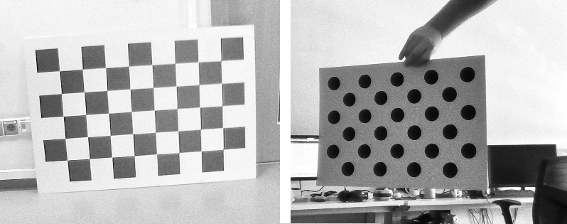
The camera calibration process involves capturing images of a calibration pattern and determining the relationship between its 3D points and their corresponding 2D projections in the image. The calibration pattern can be a chessboard, a circle grid, or any other pattern with known dimensions:

Examples of patterns. Source: Own materials
Note: Before starting the calibration process, determine the calibration pattern’s size and measure the relevant dimensions (in meters). The required measurements depend on the pattern type: * Chessboard: Count the number of inner corners (where black squares meet), e.g., 8×5, and measure the square size, e.g., 0.1 m, * Circle grid: Count the number of circles in the first two rows and the last column, e.g., 9×3, and measure the distance between two neighbouring circles, e.g., 0.21 m.
As a result of the calibration process, we can obtain:
Intrinsic parameters of the camera: focal length principal point (optical center):
    [fx  0 cx]
K = [ 0 fy cy]
    [ 0  0  1]
Focal Length (fx, fy): Determines the field of view. A higher focal length narrows the view, while a lower one widens it.
Optical Center (cx, cy): The principal point where the optical axis intersects the sensor. Small lens-sensor misalignments, such as shifts or tilts, cause slight deviations from the center.
Distortion coefficients of the camera: radial and tangential distortion coefficients,
Radial Distortion: Causes straight lines to appear curved. The distortion is more pronounced at the image’s edges.
Tangential Distortion: Occurs when the lens and image sensor are not parallel. It is less common than radial distortion.
Extrinsic parameters of the camera: rotation and translation of the camera with respect to the calibration pattern.
Rotation (R): Describes the camera’s orientation in space. The rotation matrix transforms the 3D points from the world coordinate system to the camera coordinate system.
Translation (T): Represents the camera’s position in space. The translation vector describes the camera’s position relative to the calibration pattern.
Part II: Camera calibration in ROS 2
For calibration, we will use the camera_calibration
package in ROS 2. This package provides a graphical user interface to
determine the camera’s intrinsic and extrinsic parameters. While
calibration typically involves capturing images in live mode, we will
use a bag file with pre-recorded images to simplify the process.
In ROS 2, topic names are standardized to facilitate communication between nodes. The following table lists the standard topic names for camera data:
| Topic name | Comment |
|---|---|
| image_raw | Raw data from the camera driver, possibly Bayer encoded |
| image | monochrome (grayscale), source image (distorted) |
| image_color | color (RGB or BGR), source image (distorted) |
| image_rect | monochrome (grayscale), rectified image (without distortions) |
| image_rect_color | color (RGB or BGR), rectified image (without distortions) |
Note: Everything we do today should be done inside the container!
💥 💥 💥 Task 💥 💥 💥
Get the
ros2_calibrationimage:Note: Before you start downloading or building the image, check
docker imagesto see if it has already been downloaded.Option 1 - Download and load the docker image with
docker load < ros2_calibration.tar.Option 2 - Build it from the source using repository.
Look at the calibration chessboard image and determine the pattern size.

Chessboard used for calibration. Source: Own materials
Run the ROS2_callibration container:
docker_run_calib.sh
IMAGE_NAME="ros2_calibration:latest" # <DOCKER IMAGE REPOSITORY>:<DOCKER IMAGE TAG>
CONTAINER_NAME="" # student ID number

xhost +local:root

XAUTH=/tmp/.docker.xauth
if [ ! -f $XAUTH ]
then
    xauth_list=$(xauth nlist :0 | sed -e 's/^..../ffff/')
    if [ ! -z "$xauth_list" ]
    then
        echo $xauth_list | xauth -f $XAUTH nmerge -
    else
        touch $XAUTH
    fi
    chmod a+r $XAUTH
fi

docker stop $CONTAINER_NAME || true && docker rm $CONTAINER_NAME || true

docker run -it \
    --env="ROS_AUTOMATIC_DISCOVERY_RANGE=LOCALHOST" \
    --env="DISPLAY=$DISPLAY" \
    --env="QT_X11_NO_MITSHM=1" \
    --volume="/tmp/.X11-unix:/tmp/.X11-unix:rw" \
    --env="XAUTHORITY=$XAUTH" \
    --volume="$XAUTH:$XAUTH" \
    --privileged \
    --network=host \
    --name="$CONTAINER_NAME" \
    $IMAGE_NAME \
    bash
Note: The container should set up the ROS 2 environment automatically. If not, run the following commands:
source /opt/ros/jazzy/setup.bashto source the ROS 2 environment, andexport ROS_AUTOMATIC_DISCOVERY_RANGE=LOCALHOSTto limit the topic discovery to the local machine.
- Build the package:
colcon build --packages-select robotics_camera_calibration- Source the workspace:
source install/setup.bash- Check topics available in the bag file:
ros2 bag info data/calibration_bag/- Fill in missing parameters and run the calibration node:
ros2 run camera_calibration cameracalibrator \
    -p chessboard \
    --size <DEFINE_PATTERN_SIZE> \
    --square 0.065 \
    --no-service-check \
    --ros-args \
-r image:=<DEFINE_IMAGE_TOPIC_LEFT_CAMERA>- Attach the second terminal to the container:
docker exec -it <your_container_name> bash- Play the calibration bag:
ros2 bag play data/calibration_bag/Observe the calibration process - the algorithm will detect the chessboard corners.
When the “Calibration” button becomes active, click it to start the calibration process. In this step, the algorithm compares detected corners with real-world patterns to minimise reprojection error.

When
calibration is finished, the calibrate button is green. Source: Own
materials
- After the calibration process is complete, go to the terminal where the calibration node is running and check the calibration results.
Note: If the bag player is finished and the calibration process is not completed, you can play the bag again to continue the calibration process. You can play the bag with slow motion to improve the calibration results using the
--rateoption (0.8 or 0.6).
Play the calibration bag again and observe the rectified images, which should be free of distortions. The node returns the re-projection error, which should be as low as possible.
Close the calibration node and the bag player.
Part III: Stereovision, double-cameras calibration, and disparity map in ROS 2

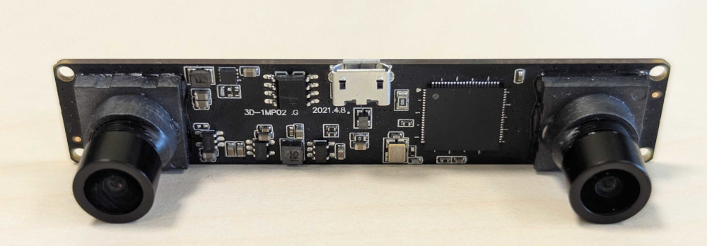
An
example stereovision camera. Source: Own materials
Stereovision uses two cameras to extract 3D information from a scene. Calibration determines the cameras’ relative position and orientation, allowing for disparity map computation.
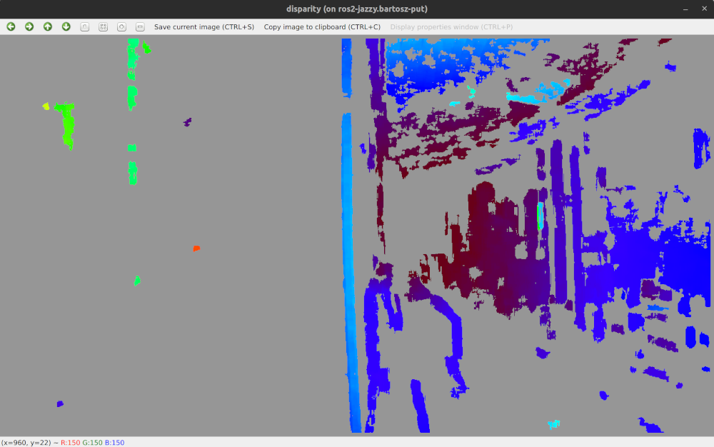
A Disparity map is a 2D representation of a scene that encodes the pixel coordinate differences between the left and right images. It is used to compute the depth map, which represents the distance between the camera and objects in the scene.
Epipolar geometry is a fundamental concept in stereovision that describes the relationship between the two cameras. It is defined by the epipolar line, which is the line connecting the camera centers and the corresponding points in the left and right images.
Depth map is a 2D representation of the scene that shows the distance between the camera and the objects in the scene. It is calculated from the disparity map using the camera calibration parameters.
The baseline is the distance between two cameras. It influences the disparity map resolution and depth map accuracy. A larger baseline enables measuring greater distances but increases the minimum measurable distance.
💥 💥 💥 Task 💥 💥 💥
- Enter the ROS2_callibration container:
docker exec -it <your_container_name> bash- Build the package:
colcon build --packages-select robotics_camera_calibration- Source the workspace:
source install/setup.bash- Set the missing parameters and run the calibration node (with two cameras):
ros2 run camera_calibration cameracalibrator \
    -p chessboard \
    --size <DEFINE_PATTERN_SIZE> \
    --square 0.065 \
    --no-service-check \
    --ros-args \
    -r left:=<DEFINE_IMAGE_TOPIC_LEFT_CAMERA> \
-r right:=<DEFINE_IMAGE_TOPIC_RIGHT_CAMERA>- Attach the second terminal to the container:
docker exec -it <your_container_name> bash- Play the calibration bag:
ros2 bag play data/calibration_bag/Observe the calibration process - the algorithm will detect the chessboard corners.
When the rosbag playing is ended, and the “Calibration” button becomes active, click it to start the calibration process.
Play the calibration bag again and observe the rectified images, which should be free of distortions
After the calibration process is complete, click the save button to save the calibration results.
Close the calibration node and the bag player.
Extract the saved calibration results using the command:
mkdir calibrationdata && tar xvf /tmp/calibrationdata.tar.gz -C calibrationdata- View the calibration results for cameras and compare them:
cat calibrationdata/left.yaml
cat calibrationdata/right.yaml
Note the differences in the projection matrices: for the right camera, the translation in the X direction (first row, last column) should be negative. Dividing this value by the focal length in the X direction determines the stereo camera baseline.
Copy them to the
src/robotics_camera_calibration/calibration_results/directory.Build the package again
colcon build --packages-select robotics_camera_calibration- Open next terminals (you need 5 in total), attach them to the container, and source the workspace in each terminal.
docker exec -it <your_container_name> bash
source install/setup.bash- Terminal 1: Run the launch file that rectifies the images and calculates the disparity map:
ros2 launch robotics_camera_calibration stereo_image_proc.launch.py- Terminal 2: Run the node that publishes calibration parameters using CameraInfo messages:
ros2 run robotics_camera_calibration stereo_info_publisher- Terminal 3: Run the node that visualizes the disparity map:
ros2 run image_view stereo_view \
    _approximate_sync:=True \
    --ros-args \
    -r /stereo/left/image:=<DEFINE_IMAGE_TOPIC_RECT_LEFT_CAMERA> \
    -r /stereo/right/image:=<DEFINE_IMAGE_TOPIC_RECT_RIGHT_CAMERA> \
-r /stereo/disparity:=/disparity- Terminal 4: Play it with the stereo images and observe the disparity map; use the loop option to play it forever:
ros2 bag play data/corridor_bag/ --loopYou should see the disparity map, which represents the pixel differences between the left and right images.

An
example disparity image. Source: Own materials
- Terminal 5: Run the node that enables parameters tuning in real-time:
ros2 run rqt_reconfigure rqt_reconfigure --force-discoverThe stereovision node provides a set of parameters that can be adjusted in real time. Tune these parameters to optimize disparity map quality. Tips for setting them can be found here.

The tool
enables real-time parameter changes. Source: Own materials
💥 💥 💥 Assignment 💥 💥 💥
To pass the course, a screenshot confirming the work done must be uploaded to the eCourses platform. It must include:
a visible disparity map
a visible list of parameters tuned in the rqt_reconfigure tool.